Quantcast
Channel: insulation Archives | EEP - Electrical Engineering Portal
Viewing all 46 articles
Browse latest View live

Inspection of electrical installations in home (2)

$
0
0
Inspection of electrical installations in home

Inspection of electrical installations in home


Continued from part I – Inspection of electrical installations in home (part 1)


Is a Periodic Inspection Needed?

Every installation deteriorates with use and age. Therefore, one must ensure that the safety of users is not put at risk and that the installation remains in a safe and serviceable condition.

Let’s have a closer look at the principal parts of the installation that play an important role in the safety of an existing electrical installation.

Contacts

Bad contacts

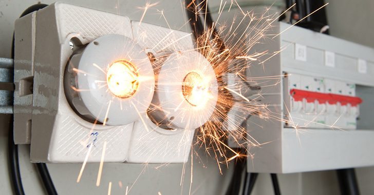
Bad contacts generate heating and sparking


In case of a bad contact, the resistance of the contact increases, causing a temperature rise. When this happens on a small surface, there is a limited heat drain and the temperature rises even more. Soon the insulation or other materials in the vicinity will lose their properties and a fire can occur.

One study demonstrated that a bad contact of 0.5 ohm rose to 1 ohm after one week and to 10 ohm after one year. The tables below give a good indication of the amount of heat generated by bad contacts compared to contacts in good condition.

Values with a good connection:

Current  (A)Voltage drop (mV)Heat developed (mW)
204 -1080 – 200
153 – 845 – 120
102 – 520 – 50
51 – 35 – 15
0.80.15 – 0.40.1 – 0.3

Values with a good bad connection:

Current (A)Voltage drop (mV)Heat developed (mW)
201,000 – 2,00020,000 – 40,000
151,200 – 1,40018,000 – 36,000
101,500 – 3,00015,000 – 30,000
52,000 – 4,00010,000 – 2,0000
0.84,000 – 7,0003,000 – 5,000

One of the best methods of verifying this condition, and even visualising it, is to carry out thermographic controls. Thermography is a non-contact method for measuring temperature based on the fact that every body emits electromagnetic radiation.

Damaged miniature circuit breakers

Damaged miniature circuit breakers due to the bad contacts or device itself

Wiring

There are two types of risks involving wiring:
  • External exposure of the cable to a fire originating in other combustible materials. The cables consist primarily of insulation material (70%), which means that there is a lot of combustible material available.
  • Internal overheating due to overloads or short circuits in cables.

There are over 9,000 electrical fires across the UK each year. More than a third of these fires are caused by inadequate or faulty wiring. A periodic inspection and testing of cable condition could be a lifesaver.

An American study revealed that the leading first ignited item in residential electrical fires is the insulation around electrical wires and cables (30.2%). The study showed that 38% of all deaths from fires in residential buildings came from insulation around electrical wires. In most cases, the fires caused by defective or worn insulation were closely related to old electrical wiring.

Arcs caused by short circuits due to defective or worn insulation or from faulty, loose, or broken conductors or switches can initiate fires.

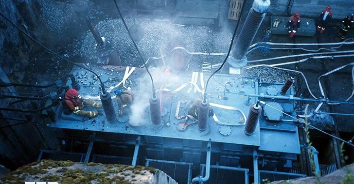
Electrical panel suffered a short circuit due to the bad conductors

Electrical panel suffered a short circuit due to the bad conductors


Aluminium wiring poses additional hazards. High temperatures that can lead to fires develop on failing circuits and bad connections. Studies have shown that aluminium-wired connections in homes have a very high probability of overheating compared to copper-wired homes. A large number of connection burnouts have occurred in aluminium-wired homes. The resulting fires involved many injuries and deaths.

When Is a Periodic Inspection Needed?

It is generally accepted that an electrical installation should be inspected every ten years. The ten-year interval is also noted in the IEC 60364. Unfortunately, the periodic inspection is not compulsory in all countries. When a circuit breaker trips frequently, or sockets, switches, or fuse panels become hot or display burn marks, an inspection and further maintenance is required.

Another occasion to carry out a periodic inspection is when modifications are made to old or existing installations. Structural changes, or changes in the use of an installation, can impair the safety of the installation. In Belgium, an inspection of the electrical installation is required when there is a change of ownership.


What To Inspect?

A periodic verification will primarily take into account the following:

  • Adequacy of the earthing and bonding
  • Suitability of the switch gear and control gear
  • Serviceability of the equipment (switches, socket outlets, light fittings) by careful examination for signs of overheating
  • The wiring system and its condition (old types of cables, insulation of the cables)
  • Provision for RCDs
  • Presence of adequate identification and notices
  • Extent of any wear and tear, damage, or other indications
  • Changes in the use of the premises that can lead to deficiencies in the installation

As with the initial verification, it is necessary to carry out inspection, tests, and measurements. The measurements will give a good indication of the status of the electrical installation and particularly of the cables and contacts.

Some tests will have to be carried out without the supply connected, while others can only be performed with the installation energized.

Some of the tests that can be carried out with the supply connected:
  • Continuity of the protective conductors
  • Equipotential bonding
  • Earth electrode resistance
  • Earth-fault loop impedance
  • Correct operation of the RCDs
  • Correct operation of switches and isolators


Considering the importance of cables and contacts in an electrical installation, testing of their condition requires that tests to be carried out without the supply connected.

How To Test The Quality Of The Cables

The most important test carried out during the verification of an electrical installation is related to the quality of insulation. As noted earlier, insulation deteriorates with age. In addition, some insulation will have been subjected to mechanical wear and tear, cables may have been subjected to overloads causing excessive heat, et cetera.

What happens when the insulation deteriorates? The current flowing through the insulation will increase and can reach dangerous values, causing electrical shocks and fire. The quality and the condition of the cables is verified by measuring the insulation resistance.

How To Measure The Insulation Resistance?

Principle

Apply a stable continuous voltage for a defined period, measure the resulting current between the two parts under test, and ascertain with Ohm’s Law that the insulation resistance is higher than the minimum value required by the standards.

Measurements should be carried out with an insulation tester. An insulation tester used during the initial verification will eliminate short-circuits or short to earth faults. During periodic verifications, the insulation tester will also help test the integrity of the cables by revealing insulation failures that could result in shock and fire.

The test is made between the active conductors (phase and neutral) and the PE (protective conductor) connected to the earthing arrangement. For the purpose of this test, active conductors may be connected together. The dc voltage applied between the live conductors (de-energized) and the earthing arrangement, will cause a very small current to flow through the conductor and the insulation.

The higher the current, the lower the resistance (R=E/I). The current will increase as insulation deteriorates.

A low insulation resistance means that a leakage current is flowing through the insulation to earth. This leakage current could shock an individual if there is no RCD or if there is an accidental interruption of the Protective Earth conductor. A leakage current of 500 mA can generate enough heat to ignite the surrounding materials, involving the risk of causing a fire.

According to the IEC 60364-6, the following table applies:

Nominal circuit voltage (V)Test voltage DC (V)Insulation resistance (MΩ)
SELV and PELV250≥ 0.5
Up to and including 500 V, including FELV500≥ 1.0
Above 500 V1,000≥ 1.0

The insulation resistance, measured with the test voltage indicated in the table, is satisfactory if each circuit (with the appliances disconnected) has an insulation resistance not less than the appropriate value given in the table.

However, where a reading of less than 2 MW is recorded for an individual circuit, there is the possibility of defective insulation and it may be necessary to replace the cable.


Costs Involved

The cost of an insulation tester is not excessive and the extra time needed to measure the insulation resistance when carrying out verification is small compared to the profit of having a good visualization of the quality of the electrical installation.

Bad contacts can be remedied and bad cables replaced before a fire breaks out.

Conclusions and Recommendations

One cannot state unequivocally that all old wiring in the homes is a hazard. The main concern is to determine the condition of the cables and their insulation. Insulation becomes damaged when it is pierced or undergoes other mechanical damage as well as when a circuit is overloaded. The cable becomes hot and the insulation will crack after a time.

It is clear that a verification of an existing electrical installation without testing does not providing a sufficient indication of the state of the most important safety issue of an existing installation, i.e. the insulation quality of the cables. It will only reveal visible damage to the electrical equipment due to wear and tear and mechanical damage. When no tests and
measurements are carried out, it could give a false sense of safety.

Therefore, verification should always be comprised of an inspection and tests. Many home fires can be avoided if the electrical installation is tested with an insulation tester and if cables that are not up to standard are replaced. To avoid the problem of bad contacts, it is good practice to replace the entire cable when a section of a cable is damaged.

It is good practice to remove obsolete cables to reduce potential fuel load. There is better fire performance using the new vinyl compounds compared to the traditional compounds. Due to the specific hazards related to the use of aluminium wiring (especially in homes in Eastern Europe), it is good practice to replace them with copper wiring at the first sign of degradation or bad contacts.

Resource: Paul De Potter – Inspection of electrical installations in homes

Bibliography used:

• IEC 60364-6: Low-voltage installations / Part 6: Verification
• Towards improved electrical installations in European homes — European Copper Institute
• Overview of electrical safety in 11 countries — European Copper Institute
• US Fire Administration Publications
• ESFI (Electrical Safety Foundation International) Publications
• Reducing the fire hazard in aluminium-wired homes – J. Aronstein, Ph.D.

Measurement of insulation resistance (IR) – Part 2

$
0
0
Fluke insulation resistance tester up to 10kV

Fluke insulation resistance tester up to 10kV - Allows testing of high voltage systems such as control gears, engines, generators and cables. It can be adjusted to all testing voltages that are specified in IEEE 43-2000. Ideal for Electricity Board and industrial companies for predictive and preventive maintenance.


Continued from first part: Measurement of insulation resistance (IR) – Part 1

1. IR Values For Electrical Apparatus & Systems

(PEARL Standard / NETA MTS-1997 Table 10.1)

Max.Voltage Rating Of Equipment Megger SizeMin.IR Value
250 Volts500 Volts25 MΩ
600 Volts1,000 Volts100 MΩ
5 KV2,500 Volts1,000 MΩ
8 KV2,500 Volts2,000 MΩ
15 KV2,500 Volts5,000 MΩ
25 KV5,000 Volts20,000 MΩ
35 KV15,000 Volts100,000 MΩ
46 KV15,000 Volts100,000 MΩ
69 KV15,000 Volts100,000 MΩ

One Meg ohm Rule for IR Value for Equipment

Based upon equipment rating:

< 1K V = 1 MΩ minimum
>1KV = 1 MΩ /1KV

As per IE Rules-1956

At a pressure of 1000 V applied between each live conductor and earth for a period of one minute the insulation resistance of HV installations shall be at least 1 Mega ohm or as specified by the Bureau of Indian Standards.

Medium and Low Voltage Installations- At a pressure of 500 V applied between each live conductor and earth for a period of one minute, the insulation resistance of medium and low voltage installations shall be at least 1 Mega ohm or as specified by the Bureau of Indian Standards] from time to time.

As per CBIP specifications the acceptable values are 2 Mega ohms per KV

2. IR Value for Transformer

Insulation resistance tests are made to determine insulation resistance from individual windings to ground or between individual windings. Insulation resistance tests are commonly measured directly in megohms or may be calculated from measurements of applied voltage and leakage current.

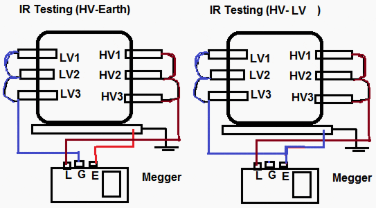
The recommended practice in measuring insulation resistance is to always ground the tank (and the core). Short circuit each winding of the transformer at the bushing terminals. Resistance measurements are then made between each winding and all other windings grounded.

Insulation resistance testing: HV - Earth and HV - LV

Insulation resistance testing: HV - Earth and HV - LV


Transformer windings are never left floating for insulation resistance measurements. Solidly grounded winding must have the ground removed in order to measure the insulation resistance of the winding grounded. If the ground cannot be removed, as in the case of some windings with solidly grounded neutrals, the insulation resistance of the winding cannot be measured. Treat it as part of the grounded section of the circuit.

We need to test winding to winding and winding to ground ( E ).For three phase transformers, We need to test winding ( L1,L2,L3 ) with substitute Earthing for Delta transformer or winding ( L1,L2,L3 ) with earthing ( E ) and neutral ( N ) for wye transformers.

IR Value for Transformer
(Ref: A Guide to Transformer Maintenance by. JJ. Kelly. S.D Myer)
TransformerFormula
1 Phase TransformerIR Value (MΩ) = C X E / (√KVA)
3 Phase Transformer (Star)IR Value (MΩ) = C X E (P-n) / (√KVA)
3 Phase Transformer (Delta)IR Value (MΩ) = C X E (P-P) / (√KVA)
Where C= 1.5 for Oil filled T/C with Oil Tank, 30 for Oil filled T/C without Oil Tank or Dry Type T/C.

Temperature correction Factor (Base 20°C):

Temperature correction Factor
OCOFCorrection Factor
0320.25
5410.36
10500.50
15590.720
20681.00
30861.98
401043.95
501227.85

Example: For 1600KVA, 20KV/400V,Three Phase Transformer

  • IR Value at HV Side= (1.5 x 20000) / √ 1600 =16000 / 40 = 750 MΩ at 200C
  • IR Value at LV Side = (1.5 x 400 ) / √ 1600= 320 / 40 = 15 MΩ at 200C
  • IR Value at 300C =15X1.98= 29.7 MΩ

Insulation Resistance of Transformer Coil

Transformer Coil  VoltageMegger SizeMin.IR Value Liquid Filled T/CMin.IR Value Dry Type T/C
0 – 600 V1KV100 MΩ500 MΩ
600 V To 5KV2.5KV1,000 MΩ5,000 MΩ
5KV To 15KV5KV5,000 MΩ25,000 MΩ
15KV To 69KV5KV10,000 MΩ50,000 MΩ

IR Value of Transformers

VoltageTest Voltage (DC)  LV sideTest  Voltage (DC) HV sideMin IR Value
415V500V2.5KV100MΩ
Up to 6.6KV500V2.5KV200MΩ
6.6KV to 11KV500V2.5KV400MΩ
11KV to 33KV1000V5KV500MΩ
33KV to 66KV1000V5KV600MΩ
66KV to 132KV1000V5KV600MΩ
132KV to 220KV1000V5KV650MΩ

 Steps for measuring the IR of Transformer:

  • Shut down the transformer and disconnect the jumpers and lightning arrestors.
  • Discharge the winding capacitance.
  • Thoroughly clean all bushings
  • Short circuit the windings.
  • Guard the terminals to eliminate surface leakage over terminal bushings.
  • Record the temperature.
  • Connect the test leads (avoid joints).
  • Apply the test voltage and note the reading. The IR. Value at 60 seconds after application of the test voltage is referred to as the Insulation Resistance of the transformer at the test temperature.
  • The transformer Neutral bushing is to be disconnected from earth during the test.
  • All LV surge diverter earth connections are to be disconnected during the test.
  • Due to the inductive characteristics of transformers, the insulation resistance reading shall not be taken until the test current stabilizes.
  • Avoid meggering when the transformer is under vacuum.


Test Connections of Transformer for IR Test (Not Less than 200 MΩ)

Two winding transformer
1. (HV + LV) – GND
2. HV – (LV + GND)
3. LV – (HV + GND)

Three winding transformer
1. HV – (LV + TV + GND)
2. LV – (HV + TV + GND)
3. (HV + LV + TV) – GND
4. TV – (HV + LV + GND)

Auto transformer (two windings)
1. (HV + LV) – GND

Auto Transformer (three winding)
1. (HV + LV) – (TV + GND)
2. (HV + LV + TV) – GND
3. TV – (HV + LV + GND)

For any installation, the insulation resistance measured shall not be less than:

  • HV – Earth 200 M Ω
  • LV – Earth 100 M Ω
  • HV – LV 200 M Ω

Factors affecting on IR value of Transformer

The IR value of transformers are influenced by

  • Surface condition of the terminal bushing
  • Quality of oil
  • Quality of winding insulation
  • Temperature of oil
  • Duration of application and value of test voltage

3. IR Value for Tap Changer

  • IR between HV and LV as well as windings to earth.
  • Minimum IR value for Tap changer is 1000 ohm per volt service voltage

4. IR Value for Electric motor

For electric motor, we used a insulation tester to measure the resistance of motor winding with earthing (E).

  • For rated voltage below 1KV, measured with a 500VDC Megger.
  • For rated voltage above 1KV, measured with a 1000VDC Megger.
  • In accordance with IEEE 43, clause 9.3, the following formula should be applied.
  • Min IR Value (For Rotating Machine) =(Rated voltage (v) /1000) + 1
Insulation resistance (IR) value for electric motor

Insulation resistance (IR) value for electric motor


As per IEEE 43 Standard 1974, 2000
IR Value in MΩ
IR (Min) = kV+1For most windings made before about 1970, all field windings, and others not described below
IR (Min) = 100 MΩFor most dc armature and ac windings built after about 1970 (form wound coils)
IR (Min) = 5 MΩFor most machines with random -wound stator coils and form-wound coils rated below 1kV

Example-1: For 11KV, Three Phase Motor.

  • IR Value =11+1=12 MΩ but as per IEEE43 It should be 100 MΩ
  • Example-2: For 415V,Three Phase Motor
  • IR Value =0.415+1=1.41 MΩ but as per IEEE43 It should be 5 MΩ.
  • As per IS 732 Min IR Value of Motor=(20XVoltage(p-p/(1000+2XKW)

IR Value of Motor as per NETA ATS 2007. Section 7.15.1

Motor Name Plate (V)Test VoltageMin IR Value
250V500V DC25 MΩ
600V1000V DC100MΩ
1000V1000V DC100MΩ
2500V1000V DC500MΩ
5000V2500V DC1000MΩ
8000V2500V DC2000MΩ
15000V2500V DC5000MΩ
25000V5000V DC20000MΩ
34500V15000V DC100000MΩ

IR Value of Submersible Motor:

IR Value of Submersible Motor
Motor Out off Well (Without Cable)IR Value
New Motor20 MΩ
A used motor which can be reinstalled10 MΩ
Motor  Installed in Well (With Cable)
New Motor2 MΩ
A used motor which can be reinstalled0.5 MΩ

5. IR Value for Electrical cable and wiring

For insulation testing, we need to disconnect from panel or equipment and keep them isolated from power supply. The wiring and cables need to test for each other ( phase to phase ) with a ground ( E ) cable. The Insulated Power Cable Engineers Association (IPCEA) provides the formula to determine minimum insulation resistance values.

R = K x Log 10 (D/d)

R = IR Value in MΩs per 1000 feet (305 meters) of cable.
K = Insulation material constant.( Varnished Cambric=2460, Thermoplastic Polyethlene=50000,Composite Polyethylene=30000)
D = Outside diameter of conductor insulation for single conductor wire and cable ( D = d + 2c + 2b diameter of single conductor cable )
d – Diameter of conductor
c – Thickness of conductor insulation
b – Thickness of jacket insulation


HV test on new XLPE cable (As per ETSA Standard)

ApplicationTest VoltageMin IR Value
New cables – Sheath1KV DC100 MΩ
New cables – Insulation10KV DC1000 MΩ
After repairs – Sheath1KV DC10 MΩ
After repairs – Insulation5KV DC1000MΩ

11kV and 33kV Cables between Cores and Earth (As per ETSA Standard)

ApplicationTest VoltageMin IR Value
11KV New cables – Sheath5KV DC1000 MΩ
11KV After repairs – Sheath5KV DC100 MΩ
33KV no TF’s connected5KV DC1000 MΩ
33KV with TF’s connected.5KV DC15MΩ


11kV and 33kV Cables between Cores and Earth

11kV and 33kV Cables between Cores and Earth


IR Value Measurement (Conductors to conductor (Cross Insulation))

  • The first conductor for which cross insulation is being measured shall be connected to Line terminal of the megger. The remaining conductors looped together (with the help of crocodile clips) i. e. Conductor 2 and onwards, are connected to Earth terminal of megger. Conductors at the other end are left free.
  • Now rotate the handle of megger or press push button of megger. The reading of meter will show the cross Insulation between conductor 1 and rest of the conductors. Insulation reading shall be recorded.
  • Now connect next conductor to Line terminal of the megger & connect the remaining conductors to earth terminal of the megger and take measurements.

IR Value Measurement (Conductor to Earth Insulation)

  • Connect conductor under test to the Line terminal of the megger.
  • Connect earth terminal of the megger to the earth.
  • Rotate the handle of megger or press push button of megger. The reading of meter will show the insulation resistance of the conductors. Insulation reading shall be recorded after applying the test voltage for about a minute till a steady reading is obtained.

IR Value Measurements:

  • If during periodical testing, insulation resistance of cable is found between 5 and 1 /km at buried temperature, the subject cable should be programmed for replacement.
  • If insulation resistance of the cable is found between 1000 and 100 /km, at buried temperature, the subject cable should be replaced urgently within a year.
  • If the insulation resistance of the cable is found less than 100 kilo ohm/km., the subject cable must be replaced immediately on emergency basis.

6. IR Value for Transmission / Distribution Line

EquipmentMegger SizeMin IR Value
S/S .Equipments5 KV5000MΩ
EHVLines.5 KV10MΩ
H.T. Lines.1 KV5MΩ
LT / Service Lines.0.5 KV5MΩ

7. IR Value for Panel Bus

IR Value for Panel = 2 x KV rating of the panel.
Example, for a 5 KV panel, the minimum insulation is 2 x 5 = 10 MΩ.

8. IR Value for Substation Equipment

Generally meggering Values of Substation Equipments are.

Typical IR Value of S/S Equipments
Equipment
Megger SizeIR Value(Min)
Circuit Breaker(Phase-Earth)5KV,10 KV1000 MΩ
(Phase-Phase)5KV,10 KV1000 MΩ

Control Circuit

0.5KV50 MΩ

CT/PT

(Pri-Earth)5KV,10 KV

1000 MΩ

(Sec-Phase)5KV,10 KV50 MΩ
Control Circuit

0.5KV

50 MΩ
Isolator(Phase-Earth)5KV,10 KV1000 MΩ
(Phase-Phase)5KV,10 KV1000 MΩ
Control Circuit0.5KV50 MΩ
L.A(Phase-Earth)5KV,10 KV1000 MΩ
Electrical Motor(Phase-Earth)0.5KV50 MΩ
LT Switchgear(Phase-Earth)0.5KV100 MΩ
LT Transformer(Phase-Earth)0.5KV100 MΩ

IR Value of S/S Equipments As per DEP Standard
EquipmentMeggeringIR Value at Commissioning Time (MΩ)IR Value at Maintenance Time
SwitchgearHV Bus200 MΩ100 MΩ
LV Bus20 MΩ10 MΩ
LV wiring5 MΩ0.5 MΩ
Cable(min 100 Meter)HV & LV(10XKV) / KM(KV) / KM
Motor & GeneratorPhase-Earth10(KV+1)2(KV+1)
Transformer Oil immersedHV & LV75 MΩ30 MΩ
Transformer Dry TypeHV100 MΩ25 MΩ
LV10 MΩ2 MΩ
Fixed Equipments/ToolsPhase-Earth5KΩ / Volt1KΩ / Volt
Movable EquipmentsPhase-Earth5 MΩ1MΩ
Distribution EquipmentsPhase-Earth5 MΩ1MΩ
Circuit BreakerMain Circuit2 MΩ / KV-
Control Circuit5MΩ-
RelayD.C Circuit-Earth40MΩ-
LT Circuit-Earth50MΩ-
LT-D.C Circuit40MΩ-
LT-LT70MΩ-

9. IR Value for Domestic /Industrial Wiring

A low resistance between phase and neutral conductors, or from live conductors to earth, will result in a leakage current. This cause deterioration of the insulation, as well as involving a waste of energy which would increase the running costs of the installation.

The resistance between Phase-Phase-Neutral-Earth must never be less than 0.5 M Ohms for the usual supply voltages.

In addition to the leakage current due to insulation resistance, there is a further current leakage in the reactance of the insulation, because it acts as the dielectric of a capacitor. This current dissipates no energy and is not harmful, but we wish to measure the resistance of the insulation, so DC Voltage is used to prevent reactance from being included in the measurement.


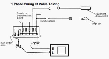
1 Phase Wiring

>The IR test between Phase-Natural to earth must be carried out on the complete installation with the main switch off, with phase and neutral connected together, with lamps and other equipment disconnected, but with fuses in, circuit breakers closed and all circuit switches closed.

Where two-way switching is wired, only one of the two stripper wires will be tested. To test the other, both two-way switches should be operated and the system retested. If desired, the installation can be tested as a whole, when a value of at least 0.5 M Ohms should be achieved.


1 Phase Wiring

1 Phase Wiring


3 Phase Wiring

In the case of a very large installation where there are many earth paths in parallel, the reading would be expected to be lower. If this happens, the installation should be subdivided and retested, when each part must meet the minimum requirement.


3 Phase Wiring

3 Phase Wiring


The IR tests must be carried out between Phase-Phase-Neutral-Earth with a minimum acceptable value for each test of 0.5 M Ohms.

IR Testing for Low voltage
Circuit voltageTest voltageIR Value(Min)
Extra Low Voltage250V DC0.25MΩ
Up to 500 V except for above500 V DC0.5MΩ
500 V To 1KV1000 V DC1.0MΩ

Min IR Value = 50 MΩ / No of Electrical outlet. (All Electrical Points with  fitting & Plugs)
Min IR Value = 100 MΩ / No of Electrical outlet. (All Electrical Points without fitting & Plugs).

Required Precautions

Electronic equipment like electronic fluorescent starter switches, touch switches, dimmer switches, power controllers, delay timers could be damaged by the application of the high test voltage should be disconnected.

Capacitors and indicator or pilot lamps must be disconnected or an inaccurate test reading will result.

Where any equipment is disconnected for testing purposes, it must be subjected to its own insulation test, using a voltage which is not likely to result in damage. The result must conform with that specified in the British Standard concerned, or be at least 0.5 M Ohms if there is no Standard.

Meggering (insulation resistance testing) of dry-type power transformer

$
0
0
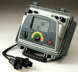
MEGGER - Insulation resistance test device

MEGGER - Insulation resistance test device

The insulation resistance test (meggering) is of value for future comparison and also for determining if the transformer is to be subjected to the applied voltage test.The winding insulation resistance test is a DC high voltage test used to determine the dryness of winding insulation system. The test measures the insulation resistance from individual windings to ground and/or between individual windings.

The measurement values are subject to wide variation in design, temperature, dryness and cleanliness of the parts. This makes it difficult to set minimum acceptable insulation resistance values that are realistic for wide variety of insulation systems that are in use and performing satisfactorily. If a transformer is known to be wet or if it has been subjected to unusually damp conditions, it should be dried before the application of the applied voltage test.

Low readings can sometimes be brought up by cleaning or drying the apparatus. The insulation resistance test should be performed at a transformer temperature as close as possible or at 20 °C. Test conducted at other temperature should be corrected 20°C with the use of temperature correcting factor.

The test equipment is calibrated to read in Megohm and commonly know as a HV Megger. Typical maximum test set voltage values may be 1kV, 5kV or 15kV. The 30kV Megger is also available.

Duration of the test voltage shall be 1 minute. In the absence of manufacture’s recommended values, the following readings may be used. Refer to Table 1.

Table 1Transformer Insulation Resistance Acceptance Testing

Winding Insulation Class, kVInsulation Resistance, MΩ*
1.2600
2.51000
5.01500
8.72000
153000

* Normally dried transformers may be expected to have readings 5 to 10 times the above minimum values.

Important Notes:

  1. Table 1 was sourced from IEEE C57-94-1982 Recommended Practice for Installation, Operation and Maintenance of Dry-type General Purpose Distribution and Power Transformer. Table 6 differs from NETA Table 100.5 figures for transformer Insulation Resistance Acceptance Testing values. There is no industry consensus for satisfactory values.
  2. Other references noted a general rule of thumb for acceptable insulation values at 1MΩ per 1kV of nameplate rating plus 1MΩ.
  3. Under no condition should the test be made while the transformer is under vacuum.
  4. The significance of values of insulation resistance test requires some interpretation depending on design, dryness and cleanliness of the insulation involved. It is recommended that the insulation resistance values be measured during periodic maintenance shutdown and trended. Large variation in the trended values should be investigated for cause.
  5. Insulation resistance may vary with applied voltage and any comparison should be made with the same measurements at the same voltage and as close as possible to the same equipment temperature and humidity as practically possible.

Insulation Resistance Test Procedure:

  1. Isolate the equipment, apply working grounds to all incoming and outgoing cables and disconnect all incoming and outgoing cables from the transformer bushing terminals connections. Disconnected cables should have sufficient clearance from the switchgear terminals greater that the phase spacing distance. Use nylon rope to hold cable away from incoming and outgoing terminals as required.
  2. Ensure the transformer tank and core is grounded.
  3. Disconnect all lightning arresters, fan system, meter or low voltage control systems that are connected to the transformer winding.
  4. Short circuit all winding terminals of the same voltage level together.
  5. Perform a 1 minute resistance measurements between each winding group to the other windings and ground.
  6. Remove all shorting leads after completion of all test.

Table 2Insulation Resistance Test Connections for Two Winding Transformer

Test No.Single-phase transformerThree-phase transformer
1High voltage winding to low voltage winding and groundHigh voltage winding to low voltage winding and ground
2High voltage winding to low voltage windingHigh voltage winding to low voltage winding
3High Voltage winding to groundHigh voltage winding to ground with low voltage winding to guard
4Low Voltage winding to high voltage winding and groundLow voltage winding to high voltage winding and ground
5Low voltage winding to groundLow voltage winding to ground and high voltage winding to guard
Resource: Substation Commisioning Course – Module for Dry-type power transformer by R. Lee

Fundamental Concepts of Insulation Testing

$
0
0
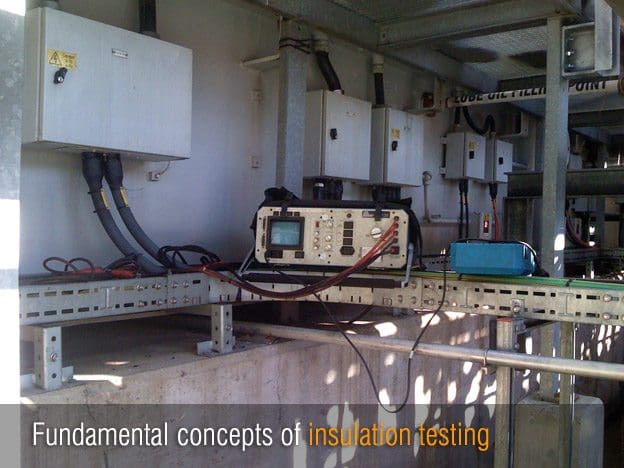
Fundamental concepts of insulation testing

Fundamental concepts of insulation testing (on photo Digital Surge/ HiPot / Resistance Tester on site)


Introduction

Probably 80% of all testing performed in electrical power systems is related to the verification of insulation quality. This technical article briefly describes the fundamental concepts of insulation testing including – insulation behavior, types of tests, and some test procedures.


AC or DC?

Most electrical equipment in utility, industrial, and commercial power systems uses either 50Hz or 60Hz alternating current. Because of this, the use of an alternating current source to test insulation would appear to be the logical choice.

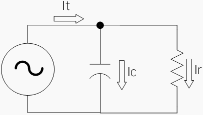
Insulation with an AC voltage applied

Figure 1 - Insulation with an AC voltage applied


However, insulation systems are extremely capacitive. For this and other reasons, DC has found a large niche in the technology. Before we can really evaluate the value of one system as opposed to the other (e.g. AC vs DC), let us examine how each type of voltage affects insulation.


Insulation Current Flow (AC)

Insulation may be simply modeled as a capacitor in parallel with a resistor as shown in Figure 1. The current flow that results will comprise two components: the capacitive current (Ic) and the resistive current (Ir).

Insulation current with AC voltage applied

Figure 2 - Insulation current with AC voltage applied


Figure 2 shows the time domain graph of the two currents. For good insulation:

  • Ic ≥ 100 x Ir
  • Ic leads Ir by close to 90°

Insulation Current Flow (DC)

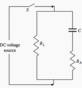
When DC current is involved, insulation may be modeled in a slightly different way. Consider Figure 3 below:

Insulation with DC voltage applied

Figure 3 - Insulation with DC voltage applied


When switch S1 is closed, the DC supply is connected to the insulation system. In the DC model an extra capacitor has been added (dashed lines). The current that flows through this new capacitor is called the dielectric absorption current (Ida) and will be explained later.

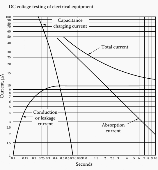
Figure 4 show the time relationship for these three currents. The following paragraphs explain each of the three currents.

DC current flow in good insulation

Figure 4 - DC current flow in good insulation


Capacitive Current (Ic)

The capacitive current charge the capacitance in the system. It normally stops flowing a few seconds (at most) after the DC voltage is applied. The short burst of capacitive current flow may put a rather substantial stress on any test equipment that is applied to very large insulation systems such as cables or large rotating machine.


Dielectric Absorption Current (Ida)

The applied insulation voltage puts a stress on the molecules of the insulation. The positive side of the molecules are attracted to the negative conductor and the negative side of the molecules are attracted to the positive conductor.

The result is an energy that is supplied to realign the molecules much like force will realign a network of rubber bands. Like Ic, Ida usually dies off fairly quickly as the molecules realign to their maximum extent.


Resistive (Leakage) Current (Ir)

This is the electron current flow that actually passes through the insulation. In good insulation the resistive current flow will be relatively small and constant.

In bad insulation the leakage current may be fairly large and it may actually increase with time.

Resource: TECHNICAL BULLETIN — 012a Principles of Insulation Testing by Cadick Corporation

Basics of 3-phase Induction Motor (part 2)

$
0
0
Basics of 3-phase Induction Motor (part 2)

Basics of 3-phase Induction Motor (part 2)


Continued from first partBasics of 3-phase Induction Motor (part 1)

For the purpose of standardization, the preferred rated voltages of three phase induction motor shall be in accordance with IS 12360: 1988.

The voltages for three phases, 50 Hz motors are: 415 V, 3.3 kV, 6.6 kV and 11 kV.

As per Motor voltage ratings are defined by NEMA MG 1, Motors and Generators (Ref. 1), and ANSI C50.41, Polyphase Induction Motors for Power Generating Stations (Ref.2). According to ANSI C50.41, Section 6.3, preferred voltage ratings are as follows:

460V; 2300V; 6600V
575V; 4000V; 13,200V

Note that these ratings do not correspond exactly to the standard ANSI C84.1 (Ref. 16) nominal system voltages of 480, 600, 2400, 4160, 6900, and 13,800V. Instead, each of these ratings is roughly 4 percent lower than the nominal system voltage. The reason for this is to provide some allowance for voltage drop.

For Coordination of Voltages and Output of three-phase induction motors it is recommended that the minimum rated output should be greater than the limits given below in terms of the rated voltage:
  • 2 < Voltage < 3.3 for and up to 100kW
  • 3.3 < Voltage < 6.6 for and up to 200kW
  • 6.6 < Voltage < 11 for and up to 1000kW.

This is the voltage rating given by IS-325 Three phase induction motor Specification but this cannot be followed in all cases as there have been cases where motors of 150kW being supplied by 415V and 160kW to 4500kW being supplied by 11kV.Now here comes the application of motor in picture & the load torque requirement of the concerned motor. Torque developed in Induction motor is directly proportional to the square of EMF induced in rotor. At standstill the EMF induced in rotor is almost equal to applied voltage to stator and in running condition the EMF induced in rotor is slip times the applied voltage to stator.

If concerned Motor is used as compressors for chillers or any application which does not require very high starting torque and is of say 400kW then whether we have more voltage or low voltage that does not matter. So we can use either 11kV for this as given by IS or even contradict it and use 6.6kV.For 11kV supply voltage will be less compared to 6.6kV supply but in both cases the load torque requirement will be met.

But if the same motor is used as a grinder motor in a refinery or any high starting torque application then you cannot feed it with 0.415kV supply as load torque requirement will not be met. We will find that load torque requirement is met at 11kV.

Because of more voltage requirement load torque requirement was not met at 0.415kV so next higher voltage level was selected even 6.6kV would have done if available.

Now question is how to find load torque requirement?

If electric motor is driving any pump/compressors then the load torque characteristics of pump/compressor is prepared by mechanical engineering department and electric motor vendor gives his load torque characteristics for required kW at a particular voltage level.

Electrical department matches the two characteristics if found not matching then other voltage level is selected whose load torque characteristics matches.


So after making a detailed study of:

- 1 - Manufacturing feasibility with respect to costing of motor. (For low kW HT machine insulation cost will be more. So more money is required.) Transformers with large motors connected, 25% – 100% of the ONAN rating, need special evaluation.

The voltage drop on the system during starting must be calculated balancing the impedance of the transformer and inrush of the motor to best match the voltage drop and short circuit needs of the system. In addition the transformer manufacturer may need to enhance the internal bracing of the transformer to accommodate the shock loading as a result of the motor starting current.

- 2 - Load torque requirement. HT motor has high Starting torque because of more voltage. So load torque requirement or application has to be studied.

- 3 - So depending upon application we deviate from IS codes in this regard.

- 4 - So we define motor utilization voltage in our DBR at the starting of project keeping in mind the above mentioned points.

As a general standard engineering practice the following utilization voltage is adopted for 3 Phase motors especially in power plants:

Motor type & ratingVoltageNo of Phases & FrequencyGrounding
AC Motor above 180kW6.6kV3Ph, 50HzNon effectively earthed
AC Motor upto 180kW415V3Ph, 50HzEffectively earthed
DC Motors220V or 110V2 Wire DCUnearthed
Why anti condensation heating or space heaters are employed when a three phase induction motor is not under operation?

Often the motors are kept in a store for some time or they are transported under very damp conditions and in such cases, the insulation resistance generally becomes low and it is dangerous for the motor to he connected up before the condition has been rectified.

IEEE 43 places special emphasis on determining the insulation condition of such machines before energizing and even before conducting a high-voltage test. This can be determined by the insulation test as noted below.

Insulation resistance of the windings is a measure to assess the condition of insulation and its suitability for conducting a high-voltage test or for energizing the machine. A low reading may suggest damage to the insulation, faulty drying or impregnation or absorption of moisture. The insulation resistance may be measured according to the procedure laid down in IEEE 43 between the open windings and between windings and the frame by employing a direct-reading ohm meter (megger).

The recommended minimum insulation resistance of the machine is obtained by the following empirical formula:

Rm=kV+1

Where:
R = recommended minimum insulation resistance in MR (mega ohms) of the entire machine windings, at 40°C or 1 MR per 1000 V plus 1 M Ω, and
kV = rated machine voltage in kV

At the site, when commissioning a new or an existing motor after a long shutdown, it must have a minimum insulation level according to the above equation. An 11 kV motor, for instance, must have a minimum insulation of 12 MΩ. In normal practice, it is observed that when first measured the resistance reading may show more than the minimum value and may mislead the operator, while the winding condition may not be adequate for a high voltage test or an actual operation.

One must therefore ensure that the winding condition is suitable before the machine is put into operation. For this purpose, the polarization index (PI), which is determined from the insulation test data only as noted below, is a useful pointer. It must be evaluated at site while conducting the insulation test then compared with the manufacturer’s reference data for the machine to assess the condition of insulation at site and its suitability for operation.

This is usually a site test, but to establish a reference record of the machine, it is also carried out at the works on the completed machine and test records furnished to the user.


Drying Out

If the measured insulation resistance of the motor is less than 1 MΩ/kV with a minimum of 1 MΩ when the machine is cold, it should first be dried out by anti condensation heater before full voltage is applied to the terminals of the motors.


References:

1. NEMA MG-1.
2. Industrial Power Engineering and Application Hand Book by K C Agarwaal.
3. Industrial Power System Hand Book by Shoaib Khan.
4. Theory and Calculation of Alternating Current Phenomena by Charles Proteus Steinmetz
5. Motor protection relay (MM30) manual from L&T

Right Choice of Dry Type or Liquid-Filled Transformer

$
0
0
Right Choice of Dry Type or Liquid-Filled Transformer

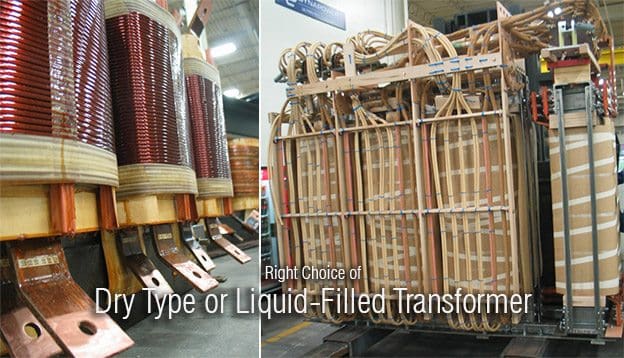
Right Choice of Dry Type or Liquid-Filled Transformer (on photo Dynapower Corporation transformers)

Content

1. Two Types of Transformers
2. Cooling and insulating system
3. Losses
4. Operating Life of Transformer
5. Maintainability
6. Repairability
7. Core/Coil Reclamation and Recycling
8. Operating Sound Level and Noise Pollution
9. Footprint
0. Conclusion


Two Types of Transformers

Information on the pros and cons of the available types of transformers frequently varies depending upon what information is made available by the manufacturer. Nevertheless, there are certain performance and application characteristics that are almost universally accepted.

Basically, there are two distinct types of transformers: Liquid insulated and cooled (liquid-filled type) and non liquid insulated, air or air/gas cooled (dry type). Also, there are subcategories of each main type.

For liquid-filled transformers, the cooling medium can be conventional mineral oil. There are also wettype transformers using less flammable liquids, such as high fire point hydrocarbons and silicones.

Liquid-filled transformers are normally more efficient than dry-types, and they usually have a longer life expectancy. Also, liquid is a more efficient cooling medium in reducing hot spot temperatures in the coils. In addition, liquid-filled units have a better overload capability.

There are some drawbacks, however.

For example, fire prevention is more important with liquid-type units because of the use of a liquid cooling medium that may catch fire. (Dry-type transformers can catch fire, too.) It’s even possible for an improperly protected wet-type transformer to explode.

And, depending on the application, liquid-filled transformers may require a containment trough for protection against possible leaks of the fluid.

Arguably, when choosing transformers, the changeover point between dry-types and wet-types is between 500kVA to about 2.5MVA, with dry-types used for the lower ratings and wet-types for the higher ratings.

Important factors when choosing what type to use include where the transformer will be installed, such as inside an office building or outside, servicing an industrial load.

Dry-type transformers with ratings exceeding 5MVA are available, but the vast majority of the higher-capacity transformers are liquid-filled. For outdoor applications, wet-type transformers are the predominate choice.

The flowing Table shows losses in dry type and oil filled type transformers:


Table: Comparison of Losses: Oil type and dry type

(Oil Transformer) LossesDry Type Transformer Losses
KVAHalf Load (W)Full Load (W)KVAHalf Load (W)Full Load (W)
50024654930500500010000
75039507900750750015000
1000436087201000820016400
150069401388015001125022500
200081551631020001320026400

Purchases of transformers are often based on the first cost (without any consideration of long-term economics) when transformer evaluation and purchase decisions are not made by the end-user.

This is particularly true when agents or electrical contractors make purchase decisions on the basis of temperature rise and low first cost for commercial and industrial end-users buying dry-type, pad-mounted transformers.

These agents or contractors may have little incentive to take into consideration any economic factors other than the transformer’s first cost. End-user concerns about higher first costs discourage OEMs and contractors from offering or recommending the more expensive, efficient options to customer who do not specifically request them.

Go to Content ↑

Cooling and insulating system

Because air is the basic cooling and insulating system for dry-type transformers, all dry-type transformers will be larger than liquid-immersed units for the same voltage and capacity (kilovolt/kilovolt-ampere) rating.

When operating at the same flux and current density, more material for core and coil implies higher losses and higher costs.

Dry-type high voltage transformer insulation system

Dry-type high voltage transformer insulation system - Glass polyester laminate insulation sheet

These trade-offs are inherent in the design of dry-type units, but dry-type transformers have traditionally offered certain fire-resistant, environmental, and application advantages for industrial and commercial situations.

Recent advances in liquid-filled units are reducing some of these (dry-type) advantages.

When purchased on the basis of lowest first cost, dry type transformers typically have significantly higher operating losses than the more efficient liquid filled transformers.

For this reason the major utilities seldom purchase dry type transformers. Because dry-type insulation systems lack the additional cooling and insulating properties of the oil-paper systems, for the same rating the dry-type transformers tend to be more costly, larger, and have greater losses than a corresponding liquid-immersed unit.

Go to Content ↑


Losses

2500 kVA transformer

2500 kVA transformer

Combined Losses at 100% Loading

Above graphic shows combined losses at 100% loading based on:

Liquid:Cast:Dry:
Load Losses (kW)16.3821.0018.52
No Load Losses (kW)2.667.007.55
Total Losses (kW)19.0426.0728.00

Above values are typical.

Go to Content ↑


50% Loading

At 50% loading, the no-load loss remains the same, and load loss is reduced by the inverse square:

Liquid:Cast:Dry:
Load Losses (kW)4.104.635.25
No Load Losses (kW)2.667.007.55
Total Losses (kW)6.7612.1812.25

Go to Content ↑

Costs Of Transformer Losses

Costs Of Transformer Losses – Transformer Energy Consumption:

Constants:
Energy Costs = $0.06/kWh (Conservative Value)
8760 hours = 24hrs/day * 365 days per year

Liquid:Cast:Dry:
Total Losses (kW)6.7612.1812.25
KWH Billing Rate:x$0.06$0.06$0.06
Annual Hours:x876087608760
Annual Cost of Energy due to
Losses @ 50% Load:

=

$3,553$6,402$6,439
Excess Annual Energy Costs:Base$2,849$2,886
10-Yr* Excess Energy Costs:Base$28,490$28,860

*Simple costs, assumes no interest rate or escalating energy costs

Go to Content ↑


Additional Cost Of Transformer Losses

Additional Cost Of Transformer Losses – Air Conditioning Energy Consumption:

Energy consumption by the transformer is not the only energy factor. Transformer losses are dissipated as heat, which must be removed from a controlled temperature environment by air conditioning.

Illustrated below are calculations to convert transformer losses into increased air conditioning energy consumption.

Constants:
1kW = 3415BTU/Hr
1Ton Air Conditioning = 12000BTU/Hour
1Ton Air Conditioning = 1.7kW power use

Liquid:Cast:Dry:
Total Losses (kW)6.7612.1812.25
BTU/HR/KW:x341534153415
BTU/HR:=230854159541834
BTU/HR per ton A/C:

÷

120001200012000
A/C (tons): =1.923.473.49
kW power usage per ton A/C: x1.71.71.7
kW:=3.275.895.93
Annual Hours of Operation (h):x876087608760
Annual energy usage (kWh):=286495161951916
kWH billing rate:x$0.06$0.06$0.06
Annual Cooling Costs:=$1,718.94$3,097$3,115
Excess Annual Cooling Costs:base$1,378$1,396
10-Yr Excess Energy Costs:base$13,782$13,960

Go to Content ↑

Operating Life of Transformer

Typical dry-type lifespan: 15-25 Years
Typical liquid-filled lifespan: 25-35 Years

The retirement age of transformers removed from service for a variety of reasons ranges from 14 to 35 years; the average is 25 years. However, the average life of liquidimmersed transformers that remain in service is 30 years or more.

Because liquid-filled transformers last longer than dry-type, they save on material, labor to replace, and operational impact due to outage to replace.

Go to Content ↑


Maintainability

Recommended annual maintenance for a typical dry-type transformer consists of inspection, infrared examination of bolted connections, and vacuuming of grills and coils to maintain adequate cooling and prevent buildup of flammable material.

Cleaning of the grill and coils may require the undesirable requirement of de-energizing the transformer, often leading to no cleaning. Omitting the cleaning decreases the transformer efficiency due to decreased airflow and creates a fire hazard.

Preventive maintenance for a liquid-filled transformer may consist of drawing and analyzing an oil sample. The oil analysis provides a very accurate assessment of the transformer condition – something not possible with dry-type transformers. Omitting the preventive maintenance does not decrease transformer efficiency or create a potential fire hazard.

Less-flammable liquid-filled transformers provide the best opportunity to enable maximum efficiency with the least maintenance, and provide the best diagnostics for repair/re-use rather than unforeseen failure/disposal.

Go to Content ↑


Repairability

“Coils in liquid-type units are much easier to repair than coils in dry-type transformers. Cast coils are not repairable; they must be replaced.” – Moran, Robert B. Guidelines for transformer application designs. Electrical Construction and Maintenance, May 1996.

When a transformer fails, a decision to repair or replace the transformer must be made. Liquid-filled transformers, in most situations, can be economically repaired at local independent service repair facilities.

Liquid-filled transformers provide the best opportunity to repair existing equipment rather than dispose and replace.

Example: 2500kVA Transformer – Purchase and Maintenance

LiquidCastDry
Purchase Price:$35,000$60,000$38,000
Operating Life (years):353025
Annual Maintenance:none6 hours6 hours
Annual Maintenance:none$360$360
Outage Required for Maintenance:N/AYesYes
Fire Hazard if not Maintained:NoYesYes
Repairable:YesNoYes
Annual cost to purchase and maintain:$902$1,693$1,376

Go to Content ↑

Core/Coil Reclamation and Recycling

Feature: Liquid filled transformers allow easier core/coil reclamation
Materials & Resources Benefit: Easier to recycle

Utility companies who use most of the liquid-filled transformers typically replace the coils on old transformers and continue to use them for a large percentage of their old substation transformers. The small distribution transformers are disposed/recycled when they reach an end of life.

When it comes time to decommission a transformer, recycling offsets the need for new material and provides a positive cash flow. Most components of liquid-filled and dry-type transformers can be recycled. Cast resin type transformers are an exception. Because of their construction, the materials in cast resin type transformers can be difficult and uneconomical to recycle. When a cast coil fails, the entire winding, encapsulated in epoxy resin, is rendered useless and typically ends up in a landfill.

This wastes the resource and creates additional costs for disposal, plus long-term liability exposure to the original owner.

In contrast, liquid-filled transformers can be easily recycled after their useful life. The transformer fluid can be reconditioned and used again, and the steel, copper, and aluminum can be completely and economically recycled, providing a positive cash flow.

The scrap values and disposal costs for a 2500 kVA transformer are shown below. Positive cash flows are shown in parentheses.

2500kVA Transformer

Dry TypeCast ResinLiquid Filled
Dielectric Fluid$0$0$500
Core and Coil$1100$100$1200
Tank and Fitting$400$100$400
Disposal Costs$0$400$0
Total Costs (or Savings)$1500$200$2100

Operating Sound Level and Noise Pollution

Feature: Liquid filled transformers have a lower operating sound level
Indoor Environmental Quality Benefit: Less noise pollution

Transformer types comparison - Operating sound level

Transformer types comparison - Operating sound level


Decibels is a logarithmic function, and sound pressure doubles for every three decibel  increase. Research shows that decibel levels over 60 can reduce a person’s attention  span.

A study by the American Society of Interior Designers showed that office  productivity would increase if workspaces were less noisy.

Go to Content ↑


Footprint

Feature: Liquid filled transformers have a smaller footprint
Materials and Resources Benefit: Smaller equipment reduces building size demand

Constants:
Typical cost per square foot: $25/SF

kVALiquid:Dry:Difference: $25/SF:
750kVADepth:4.6 ft5.5 ft
Width:4.6 ft8.0 ft
Sq Ft:21 ft244 ft223 ft2$575
1000kVADepth:5.2 ft5.5 ft
Width:4.8 ft8.0 ft
Sq Ft:25 ft244 ft219 ft2$475
1500kVADepth:6.3 ft5.5 ft
Width:4.4 ft8.0 ft
Sq Ft:28 ft244 ft216 ft2$400

A smaller building also has the benefit of requiring less lighting and ventilation.

Go to Content ↑

Conclusion

Use of liquid-filled transformer(s) for commercial and industrial facilities is an innovative design practice. A dry-type transformer is the standard solution for providing power in this type of design.

A total owning cost evaluation of both dry-type and liquid-filled transformers will show the lowest total owning cost choice is the installation of less-flammable liquid filled transformers.

Go to Content ↑

Resources: Best Practice Manual for transformers - Devki Energy Consultancy Pvt. Ltd.; Application for LEED Innovation & Design Points - Transformer Technology:  Liquid-Filled vs. Dry-Type

Definition of Basic Insulation Level (BIL)

$
0
0
Definition of Basic Insulation Level (BIL)

Definition of Basic Insulation Level (BIL) - photo by bob1217 @ Flickr

Introduction to BIL

Insulation levels are designed to withstand surge voltages, rather than only normal operating voltages. Since the insulation lines and equipment is protected by surge arresters draining the surges rapidly before the insulation is damaged, the arrester must operate below the minimum insulation level that must withstand the surges.

An example is shown in Figure 1a below.

The minimum level is known as the Basic Insulation Level (BIL) that must be that of all of the components of a system.

Insulation coordination

Figure 1a - Insulation coordination


Insulation values above this level for the lines and equipment in the system must be so coordinated that specific protective devices operate satisfactorily below that minimum level.

In the design of lines and equipment considering the minimum level of insulation required, it is necessary to define surge voltage in terms of its peak value and return to lower values in terms of time or duration. Although the peak voltage may be considerably higher than normal voltage, the stress in the insulation may exist for only a very short period of time.

For purposes of design, the voltage surge is defined as one that peaks in 1.5 microseconds and falls to one-half that value in 40 microseconds (thousandths of a second).

It is referred to as a 1.5/40 wave, the steep rising portion is called the wave front and the receding portion the wave tail, Figure 2.

Surge Voltage 1.5 by 4.0 Wave

Figure 2 - Surge Voltage 1.5 by 4.0 Wave

Insulation levels recommended for a number of voltage classes are listed in Table 1. As the operating voltages become higher, the effect of a surge voltage becomes less; hence, the ratio of the BIL to the voltage class decreases as the latter increases.

Table 1 – Typical Basic Insulation Levels

Basic insulation level, kV
(standard 1.5- × 40-μs wave)
Voltage class, kVDistribution classPower class (station, transmission lines)
1.23045
2.54560
5.06075
8.77595
1595110
23110150
34.5150200
46200250
69250350

*For current industry recommended values, refer to the latest revision of the National Electric Safety Code.

Distribution class BIL is less than that for power class substation and transmission lines as well as consumers’ equipment, so that should a surge result in failure, it will be on the utility’s distribution system where interruptions to consumers are limited and the utility better equipped to handle such failures.

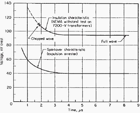
The line and equipment insulation characteristics must be at a higher voltage level than that at which the protecting arrester begins to spark over to ground, and a sufficient voltage difference between the two must exist.

The characteristics of the several type arresters are shown in the curves of Figure 3.

Sparkover Characteristics of Distribution Value / Expulsion Arresters

Figure 3 - (a) Sparkover Characteristics of Distribution Value Arresters; (b) Sparkover Characteristics of Expulsion Arresters


The impulse level of lines and equipment must be high enough for the arresters to provide protection but low enough to be economically practical.

Surges, on occasion, may damage the insulation of the protective device; hence, insulation coordination should include that of the protective devices.

As there are a number of protective devices, mentioned earlier, each having characteristics of its own, the characteristics of all of these must be coordinated for proper operation and protection.

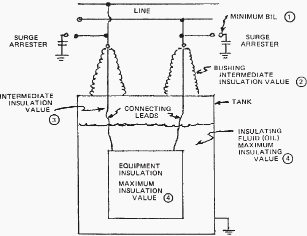
Before leaving the subject of insulation coordination, such coordination also applies within a piece of equipment itself. The insulation associated with the several parts of the equipment must not only withstand the normal operating voltage, but also the higher surge voltage that may find its way into the equipment.

So, while the insulation of the several parts is kept nearly equal, that of certain parts is deliberately made lower than others; usually this means the bushing. Since the bushing is usually protected by an air gap or arrester whose insulation under surge is lower than its own, flashover will occur across the bushing and the grounded tank.

The weakest insulation should be weaker by a sufficient margin than that of the principal equipment it is protecting; such coordinated arrangement restricts damage not only to the main parts of the equipment, but less so to parts more easily accessible for repair or replacement.

The insulation of all parts of the equipment should exceed the basic insulation level (BIL). Figure 1b.

Simplistic diagram illustrating Basic insulation level (BIL) and Insulation coordination

Figure 1b - Simplistic diagram illustrating Basic insulation level (BIL) and Insulation coordination


Resource: Power Transmission and Distribution – Anthony J. Pansini (Get this book from Amazon)

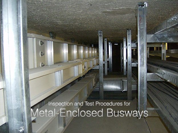
Inspection and Test Procedures for Metal-Enclosed Busways

$
0
0
Inspection and Test Procedures for Metal-Enclosed Busways

Inspection and Test Procedures for Metal-Enclosed Busways

Content

  1. Visual and Mechanical Inspection
  2. Electrical Tests
  3. Test Values
    1. Test Values – Visual and Mechanical
    2. Test Values – Electrical
  4. Tables:
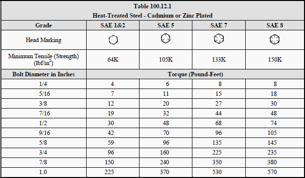
    1. TABLE 100.12 – US Standard Fasteners Bolt-Torque Values for Electrical Connections
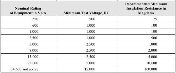
    2. TABLE 100.1 – Insulation Resistance Test Values Electrical Apparatus and Systems
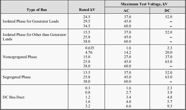
    3. TABLE 100.17 – Dielectric Withstand Test Voltages for Metal-Enclosed Bus

1. Visual and Mechanical Inspection

1. Compare equipment nameplate datawith drawings and specifications.

2. Inspect physical and mechanical condition of busway system

3. Inspect anchorage, alignment, and grounding.

4. Verify correct connection in accordance with single-line diagram.

5. Inspect bolted electrical connections for high resistance using one or more of the following methods:

  • Use of a low-resistance ohmmeter in accordance with Section 2 (Electrical Tests).
  • Verify tightness of accessible bolted electrical connections and bus joints by calibrated torque-wrench method in accordance with manufacturer’s published data or Table 100.12 below.
  • Perform thermographic survey
    (NOTE: Remove all necessary covers prior to thermographic inspection. Use appropriate caution, safety devices, and personal protective equipment.)

6. Confirm physical orientation in accordance with manufacturer’s labels to insure adequate cooling.

7. Examine outdoor busway for removal of “weep-hole” plugs, if applicable, and the correct installation of joint shield.

Go to Content ↑


2. Electrical Tests

1. Perform resistance measurements through bolted connections and busjoints with a low-resistance ohmmeter, if applicable, in accordance with Section 1 (Visual and Mechanical Inspection).

2. Measure insulation resistance of each busway, phase-to-phase and phase-to-ground for one minute, in accordance with Table 100.1 below.

3. Perform a dielectric withstand voltage test on each busway, phase-to-ground with phases not under test grounded, in accordance with manufacturer’s published data. In the absence of manufacturer’s published data, use Table 100.17.

Where no dc test value is shown in Table 100.17, ac value shall be used. The test voltage shall be applied for one minute.

4. Perform a contact-resistance test on each connection point of uninsulated busway. On insulated busway, measure resistance of assembled busway sections and compare values with adjacent phases.

5. Perform phasing test on each busway tie section energized by separate sources. Tests must be performed from their permanent sources.

6. Verify operation of busway space heaters.

Go to Content ↑


3. Test Values

3.1 Test Values – Visual and Mechanical

1. Compare bolted connection resistance values to values of similar connections. Investigate values which deviate from those of similar bolted connections by more than 50 percent of the lowest value. (7.4.1.5.1)

2. Bolt-torque levels should be in accordance withmanufacturer’s published data. In the absence of manufacturer’s published data, use Table 100.12. (7.4.1.5.2)

3. Results of the thermographic survey shall be in accordance with Section 9. (7.4.1.5.3)

Go to Content ↑


3.2 Test Values – Electrical

1. Compare bolted connection resistance values to values of similar connections. Investigate values which deviate from those of similar bolted connections by more than 50 percent of the lowest value.

2. Insulation-resistance test voltages and resistance values shall be in accordance with manufacturer’s published. In the absence of manufacturer’spublished data, use Table 100.1.

Minimum resistance values are for a nominal 1000-foot busway run. Use the following formula to convert the measured resistance value to the 1000-foot nominal value:

Busway run - minimum resistance formula

Converted values of insulation resistance less than those in Table 100.1 or manufacturer’s minimum should be investigated. Dielectric withstand voltage tests shall not proceed until insulation-resistance levels are raised above minimum values.

3. If no evidence of distress or insulation failure is observed by the end of the total time of voltage application during the dielectric withstand test, the test specimen is considered to have passed the test.

4. Microhm or dc millivolt drop values shall not exceed the high levels of the normal range as indicated in the manufacturer’s published data.

If manufacturer’s published data is not available, investigate values which deviate from those of similar bus connections and sections by more than 50 percent of the lowest value.

5. Phasing test results shall indicate the phase relationships are in accordance with system design.

6. Heaters shall be operational.

Go to Content ↑


TABLE 100.12

US Standard Fasteners – Bolt-Torque Values for Electrical Connections

Table 100.12.1 - Heat-Treated Steel - Cadmium or Zinc Plated

Table 100.12.1 - Heat-Treated Steel - Cadmium or Zinc Plated


Table 100.12.2 - Silicon Bronze Fasteners

Table 100.12.2 - Silicon Bronze Fasteners


Table 100.12.3 - Aluminum Alloy Fasteners

Table 100.12.3 - Aluminum Alloy Fasteners


Table 100.12.4 - Stainless Steel Fasteners

Table 100.12.4 - Stainless Steel Fasteners


a. Consult manufacturer for equipment supplied with metric fasteners.
b. This table is based on bronze alloy bolts having a minimum tensile strength of 70,000 pounds per square inch.
c. This table is based on aluminum alloy bolts having a minimum tensile strength of 55,000 pounds per square inch.
d. This table is to be used for the following hardware types:

  • Bolts, cap screws, nuts, flat washers, locknuts (18–8 alloy)
  • Belleville washers (302 alloy).

Go to Content ↑


TABLE 100.1

Insulation Resistance Test Values Electrical Apparatus and Systems

Insulation Resistance Test Values

Table 100.1 - Insulation Resistance Test Values for Electrical Apparatus and Systems


Go to Content ↑


TABLE 100.17

Dielectric Withstand Test Voltages for Metal-Enclosed Bus

Dielectric Withstand Test Voltages for Metal-Enclosed Bus

Table 100.17 - Dielectric Withstand Test Voltages for Metal-Enclosed Bus


Go to Content ↑

Resource: Acceptance Testing Specifications for Electrical Power Distribution Equipment and Systems – NETA 2003


Differences Between Earthed and Unearthed Cables

$
0
0
Differences Between Earthed and Unearthed Cables

Differences Between Earthed and Unearthed Cables

Introduction

In HT electrical distribution, the system can be earthed or unearthed.

The selection of unearthed or earthed cable depends on distribution system. If such system is earthed, then we have to use cable which is manufactured for earthed system. (which the specifies the manufacturer). If the system is unearthed then we need to use cable which is manufactured for unearthed system.

The unearthed system requires high insulation level compared to earthed system.

For earthed and unearthed XLPE cables, the IS 7098 part2 1985 does not give any difference in specification. The insulation level for cable for unearthed system has to be more.


Earthed System

Earlier the generators and transformers were of small capacities and hence the fault current was less. The star point was solidly grounded. This is called earthed system.

In three phases earthed system, phase to earth voltage is 1.732 times less than phase to phase voltage. Therefore voltage stress on cable to armor is 1.732 times less than voltage stress between conductors to conductor.

Where in unearthed system, (if system neutral is not grounded) phase to ground voltage can be equal to phase to phase voltage. In such case the insulation level of conductor to armor should be equal to insulation level of conductor to conductor.

In an earthed cable, the three phase of cable are earthed to a ground. Each of the phases of system is grounded to earth.

Example: 1.9/3.3 KV, 3.8/6.6 KV system


Unearthed System

Today generators of 500MVA capacities are used and therefore the fault level has increased. In case of an earth fault, heavy current flows into the fault and this lead to damage of generators and transformers. To reduce the fault current, the star point is connected to earth through a resistance. If an earth fault occurs on one phase, the voltage of the faulty phase with respect to earth appears across the resistance.

Therefore, the voltage of the other two healthy phases with respect to earth rises by 1.7 times.

If the insulation of these phases is not designed for these increased voltages, they may develop earth fault. This is called unearthed system.

In an unearth system, the phases are not grounded to earth .As a result of which there are chances of getting shock by personnel who are operating it.

Example: 6.6/6.6 KV, 3.3/3.3 KV system.

Unearthed cable has more insulation strength as compared to earthed cable. When fault occur phase to ground voltage is √3 time the normal phase to ground voltage. So if we used earthed cable in unearthed System, It may be chances of insulation puncture.

So unearthed cable are used. Such type of cable is used in 6.6 KV systems where resistance type earthing is used.

Nomenclature

In simple logic the 11 KV earthed cable is suitable for use in 6.6 KV unearthed system. The process of manufacture of cable is same.

The size of cable will depend on current rating and voltage level.

  • Voltage Grade (Uo/U) where Uo is Phase to Earth Voltage & U is Phase to Phase Voltage.
  • Earthed system has insulation grade of KV / 1.75 x KV.
  • For Earthed System (Uo/U): 1.9/3.3 kV, 3.8/6.6 kV, 6.35/11 kV, 12.7/22 kV and 19/33 kV.
  • Unearthed system has insulation grade of KV / KV.
  • For Unearthed System (Uo/U): 3.3/3.3 kV and 11/11 kV.
  • 3 phase 3 wire system has normally Unearthed grade cables and 3 phase 4 wire systems can be used earthed grade cables, insulation used is less, and cost is less.

Thumb Rule

As a thumb rule we can say that 6.6KV unearthed cable is equal to 11k earthed cable i.e 6.6/6.6kv Unearthed cable can be used for 6.6/11kv earthed system.

Because each core of cable have the insulation level to withstand 6.6kv so between core to core insulation level will be 6.6kV+6.6kV = 11kV

For transmission of HT, earthed cable will be more economical due to low cost where as unearthed cables are not economical but insulation will be good.

Generally 6.6 kV and 11kV systems are earthed through a neutral grounding resistor and the shield and armor are also earthed, especially in industrial power distribution applications.  Such a case is similar to an unearthed application but with earthed shield (sometimes called solid bonding).

In such cases, unearthed cables may be used so that the core insulation will have enough strength but current rating is de-rated to the value of earthed cables.

But it is always better to mention the type of system earthing in the cable specification when ordering the cables so that the cable manufacturer will take care of insulation strength and de rating.

Selection of Induction Motors for Industrial Applications (part 2)

$
0
0
Selection of Induction Motors for Industrial Applications (part 2) - photo by TCD Systems

Selection of Induction Motors for Industrial Applications (part 2) - photo by TCD Systems


Continued from first part: Selection of Induction Motors for Industrial Applications (part 1)


Design Considerations (cont.)

Motor Efficiency

The new IEC 60034-30 motor efficiency standard

The new IEC 60034-30 motor efficiency standard could have major energy-saving impact for industrial motors worldwide.


Though standard motors are now available with a better efficiency, this factor (motor efficency) requires due attention when making the selection of the motor for a specific application in view of substantial quantum of power consumed by the motors in the industries.

The motors running continuously should be as efficient as possible to reduce the power consumption.

Improvement of even 1% in efficiency results into saving of enormous quantum of power over a life span of the motor as well as the cost of power.

For the drives to be in service round the clock, due consideration should be given install the energy efficient motors having EFF 1 or EFF 2 class even at the higher cost, as the premium paid in the form of capital investment will be paid backhand somely in the form of cost saving due to significant energy saving when the drive will be kept in continuous service.


Ambient Temperature

As per normal standards, the motor output is given by the vendors based on 40°C ambient temperature.

If ambient temperature is expected to be high for a longer duration, then the motor is required to be checked for its suitability to maintain the specified output at higher temperature, or otherwise, the deration factor is to be applied to know the actual anticipated output at higher temperature.

In order to maintain the motor output at higher temperature as per the power requirement of driven equipment, it may be necessary that the motor with a higher frame size for the same rating is selected to avoid adverse effect of derating.


Altitude

The standard motor outputs are specified by the manufacturers for site altitude up to 1000 m.

For altitudes of more than 1000 m, the motor ratingis required to be checked for its suitability to maintain the specified output, or otherwise the duration factor is to be applied to know actual anticipated output at higher altitude. Criteria for the selection of motor remains the same as provided for higher ambient temperature.


Method of Starting and Number of Starts

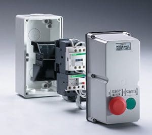
DOL starter, with enclosure, less overload, contains TeSys Model D contactor

DOL starter, with enclosure, less overload, contains TeSys Model D contactor (Ratings: 4kW, 9A, AC3, 240V, less O/L)

The starting performance of the motor depends on the method of starting deployed, i.e. directon-line, star-delta, high resistance, auto transformer, variable frequency drive, etc.

The direct-on-line starting (DOL motor starter) is the most common method adopted in which the starting current is 6-7 times the rated full load current of the motor. For high starting torque, the direct-on-line starting is essential. If the motor driving a load requiring high starting torque is started using star-delta starting, either the speed may not pick-up affecting the motor acceleration, or may take a very long time to come up to its rated speed under loaded condition inducing severe electrical and mechanical stresses respectively in the winding and core.

Where the starting torque requirement is not so critical, the star-delta starting or any other reduced voltage method of starting is used.

Where the starting with very heavy load, such as with hoist or crane drives, and speed control over a wide range is required, it is advantageous to consider the slip-ring type (or wound rotor type) motor with a drum controller starter or resistance starter.

As per modern day technology, a soft starter can also be considered for such applications.

It is essential to specify anticipated number of starts per hour or per shift of 8-hrs duration as well as number of consecutive starts required when the motor is started from cold or hot condition for facilitating the design of motor windings and selection of correct class of insulation to encounter anticipated temperature rise due to number of starts.

Large rated motors are often started via soft starters. It is desirable to explicitly specify this requirement so that the motor, compatible for such application, is designed and manufactured.


Duty Cycle

Lafert Electric motor that combines brushless permanent magnet (PM) and AC induction motor technologies.

Lafert Electric motor that combines brushless permanent magnet (PM) and AC induction motor technologies.

Selecting the proper electric motor also depends on whether the load is steady, variable over a fixed time duration, following a repetitive cycle of variation, or load with pulsating torque or shocks. The motors to be kept min service round the clock, such as driving pumps, fans, etc., may be selected on the basis of continuous load and other factors discussed in this article.

This is the Duty Cycle required to be performed by the motor.

The motors driving the equipment like automatically controlled compressors, cranes, hoists start and stop a number of times per hour and those in some machine tools start and stop many times per minute.

The Duty Cycle is a fixed repetitive load pattern over a given period of time which is expressed as the ratio of on-time to cycle period. When operating cycle is such that electric motors operate at idle or a reduced load for more than 25% of the time, Duty Cycle becomes a factor in sizing electric motors. Also, energy required to start electric motors (that is, accelerating the inertia of the electric motor as well as the driven load) is much higher than for steady-state operation, so frequent starting could overheat the electric motor.

When the motor is supposed to operated at idle or reduced load for more than 25% of the time in accordance with its operating cycle, the Duty Cycle becomes a vital factor in sizing the motor.

Also, the energy required to start the motors, i.e. during accelerating along with driven load, is much higher than that required for steady-state operation, so frequent starting, in most probability, is likely to overheat the motor.


Insulation Class

The permissible temperature rise for six insulation classes is based on the ambient temperature of 40°C as shown in following table for different class of insulating materials.

Thermal Class of InsulationNormal permissible temp. rise over 40°CNormal total temp. °CMaximum permissible temp. rise °CInsulating materials
A60100105Cotton, Silk, Impregnated/Coated paper
E75115120Synthetic enamel based on polyvinyl
acetate, Polyurethane, Epoxy on polyamide resin
B80120130Mica, Glass fibre, Asbestos with suitable
bond, viz. Synthetic resin varnishes, Epoxy resin shellac, Asphalt or bituminous compounds
F100140155Mica, Glass fibre, Asbestos with suitable bond, viz. Alkyd epoxy resin, add silicon alkyd resin
H125165180Silicon elastomers, Mica, Glass fibre, etc. with bonding substances like silicon resins
G170210225Mica porcelain, Other mica class quartz, with bonding materials of silicon resin

It may be remembered that for every 10°C rise in operating temperature, the insulation life reduces by 50% of its usual life.

Thus the temperature rise in motor is usually the dominating ageing factor of influence on the winding insulating materials and insulation systems. Hence it is essential to specify proper class of insulation for the motor based on design ambient temperature, if it is more than standard design temperature of 40°C.

The endurance of the insulation is adversely affected by many other ageing factors, such as surroundings, electrical and mechanical stresses, vibration, deleterious atmospheres and chemicals, moisture, dirt and radiation.

Will be continued very soon…

Electrical Preventive Maintenance of Air Circuit Breakers

$
0
0
Electrical Preventive Maintenance of Air Circuit Breakers

Electrical Preventive Maintenance of Air Circuit Breakers

Recommended minimum practice for preventive maintenance

Insulation

Remove and clean interphase barriers. Clean all insulating materials with vacuum and/or clean lint free rags. If it is necessary to use cleaning solvents, use only solvents recommended by the manufacturer.

Inspect for (early) signs of corona, tracking, arcing, or thermal or physical damage.

Insulation barriers (left: Interface barrier; right: Earth barrier)

Insulation barriers (left: Interface barrier; right: Earth barrier)


Ensure that insulation is left clean and dry.


Contacts

Ensure that all contacts are clean, smooth, and in proper alignment. Ensure that spring pressures are maintained according to manufacturer’s specifications. On silver contacts, discoloration is not usually harmful unless caused by insulating deposits. Clean silver contacts with alcohol or silver cleaner using non-abrasive cloths.

Contact resistance tests using micro-ohmmeter

Contact resistance tests using micro-ohmmeter (photo credit: ecmweb.com)


Manually close breaker to check for proper wipe, contact pressure, contact alignment, and to ensure that all contacts make at approximately the same time.

If possible, a contact resistance test should be performed to determine the quality of the contacts. Micro-ohmmeters, which are used to perform contact resistance tests, apply a DC current through the entire closed circuit breaker current path, including the contacts, pivot point, and stab connections of the circuit breaker. The test set read-out displays the contact resistance directly in micro-ohms.

Older breakers equipped with carbon contactors generally require very little maintenance. Examine for proper pressure, deterioration, or excessive dressing which may interfere with their proper operation.

Draw-out contacts on the circuit breaker and the stationary contacts in the cubicle should be cleaned and inspected for overheating, alignment, and broken or weak springs. Coat contact surfaces with contact lubricant to ease mating (see manufacturer’s recommendations).


Arc Interrupters

Clean all ceramic materials of loose dirt and examine for signs of moisture, make sure the assemblies are clean and dry. Examine for cracked or broken pieces. Dirt and arcing deposits may be removed by light sanding — do not use emery cloth or wire brushes which may leave conductive residue behind. Repair or replace as necessary.

Examine arc chutes for dirt and/or dust accumulations and clean as necessary. Dielectric testing of arc shields may be recommended by the manufacturer. Check air puffer for proper operation.


Operating Mechanism

Inspect for loose, broken, worn, or missing parts (consult manufacturer’s schematics for required parts). Examine for excessive wear of moving parts. Observe that operating mechanisms function properly without binding, hanging, or without delayed action.

Ensure any lubrication is done according to the manufacturer’s specifications.

Figure 1 - Cutaway view of the molded case circuit breaker

Figure 1 – Cutaway view of the molded case circuit breaker


Ensure mechanisms are clean, properly lubricated, and all bolts and screws are properly secured. Repair or replace as necessary.


Auxiliary Devices

Inspect operating devices for proper operation and general condition. Ensure all indicating devices are fully functional and properly set.

Auxiliary devices (aux. switch, alarm switch, shunt trip and unrevoltage trip device)

Auxiliary devices (aux. switch, alarm switch, shunt trip and unrevoltage trip device)


Protective relays and circuit breaker trip devices should be inspected and tested according to manufacturers’ specifications and applicable industry standards such as those issued by the Institute of Electrical and Electronics Engineers (IEEE) and the National Fire Protection Association (NFPA).

References:
  • Standard for and electrical preventive maintenance (EPM) program – The Hartford Steam Boiler Inspection and Insurance Company
  • Fuji Electric FA Components & Systems Catalogue

Why is Continuous On-line Monitoring of Partial Discharge in the Switchgear Necessary?

$
0
0
Why is Continuous On-line Monitoring Partial Discharge in the Switchgear Necessary?

Why is Continuous On-line Monitoring Partial Discharge in the Switchgear Necessary? (on photo: 11kV voltage transfromer spout failure in progress – Located by Partial Discharge survey; by highvoltagesolution.com)

What’s the condition of your switchgear?

Not sure?

You know that periodical maintenance test like partial discharge test can still leave switchgear in virtually unknown condition. Insulation defects and deterioration may very well develop in service within maintenance cycle.

These defects are often not detectable with traditional off-line tests and yet, traditionally, on-line or off-line partial discharge tests have been performed on a periodic basis commonly twice a year.

Think this is often enough?

Advantages over periodic partial discharge (PD) testing

Continuous PD monitoring has the following advantages over periodic PD testing:

1. Periodic on-line PD test could miss significant PD activities since PD activities vary by time. On-line continuous monitoring eliminates the inherent flaw of interval-based testing.

2. Trending of PD activity is one of the most important parameters for predictive diagnostics. Periodic tests will not be able to provide sufficient information for diagnostics based on trending.

3. On-line monitoring provides more accurate information than off-line testing since off-line testing conditions can differ greatly from real operating conditions.

4. Continuous on-line monitoring effectively reduces labor costs. In addition, the PD data saved in the instrument can be accessed anytime, anywhere with modern communication means.

Partial discharge test performed on site

Partial discharge test performed on site (photo credit: epowerplus.com)

Degradation of Insulation in Switchgear

Electrical insulation is subjected to electrical and mechanical stress, elevated temperature and temperature variations, and environmental conditions especially for outdoor applications.

In addition to normal operating conditions, there are a host of other factors that may trigger accelerated aging or deterioration of insulation.

Switching and lightning surges can start ionization in an already stressed area. Mechanical strikes during breaker operation can cause micro cracks and voids. Excessive moisture or chemical contamination of the surface can cause tracking.

PD Between Bus and Cubicle Wall

PD Between Bus and Cubicle Wall


Any defects in design and manufacturing are also worth mentioning. Both normal and accelerated aging of insulation produce the same phenomenon in common – Partial Discharge (PD).

Partial discharge (PD) is a localized electrical discharge that does not completely bridge the electrodes. PD is a leading indicator of an insulation problem. Quickly accelerating PD activity can result in a complete insulation failure.

Partial discharge mechanism

PD mechanism can be different depending on how and where the sparking occurs:

  1. Voids and cavities are filled with air in poorly cast current transformers, voltage transformers and epoxy spacers. Since air has lower permittivity than insulation material, an enhanced electric field forces the voids to flashover, causing PD. Energy dissipated during repetitive PD will carbonize and weaken the insulation.
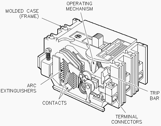
  2. Contaminants or moisture on the insulation induce the electrical tracking or surface PD. Continuous tracking will grow into a complete surface flashover.
  3. Corona discharge from sharp edge of a HV conductor is another type of PD. It produces ozone that aggressively attacks insulation and also facilitates flashover during periods of overvoltage.


Reference:  Predictive Diagnostics for Switchgear – EATON

4 Essential Qualities Of Electrical Protection

$
0
0
4 Essential Qualities Of Electrical Protection

4 Essential Qualities Of Electrical Protection (on photo protection relat panel by powersystemsmasters.com)

Fundamental Protection Requirements

In generating stations, all electrical circuits and machines are subject to faults. A fault is generally caused by the breakdown of insulation between a conductor and ground or between conductors due to a variety of reasons. The result is a flow of excess current through a relatively low resistance resulting in severe damage unless cleared quickly.

Let’s see the four main building blocks that are used to meet fundamental requirements of electrical protection:


1. Speed

When electrical faults or short circuits occur, the damage produced is largely dependent upon the time the fault persists. Therefore, it is desirable that electrical faults be interrupted as quickly as possible.

Since 1965, great strides have been made in this area. High-speed fault detecting relays can now operate in as little time as 10 milliseconds and output relaying in 2 milliseconds. The use of protection zones minimizes the requirement for time-delayed relaying.


2. Reliability

The protective system must function whenever it is called upon to operate, since the consequences of non-operation can be very severe. This is accomplished by duplicate A and B protections and duplicate power supplies.

Examples of protection relays -  Micom, Ref and Siprotec

Examples of protection relays – Micom, Ref and Siprotec

3. Security

Protections must isolate only the faulted equipment, with no over-tripping of unaffected equipment. This is accomplished by the use of over-lapping protection zones.


4. Sensitivity

The protection must be able to distinguish between healthy and fault conditions, i.e., to detect, operate and initiate tripping before a fault reaches a dangerous condition.

On the other hand, the protection must not be too sensitive and operate unnecessarily.

Some loads take large inrush starting currents, which must be accommodated to prevent unnecessary tripping while still tripping for fault conditions. The ability of relaying to fulfil the sensitivity requirement is improved through the use of protection zones.


Introduction to Protection and Control (WEBINAR)

This ABB’s webinar will define power system protective relaying and its purpose. A general overview of key concepts, protective relay classifications, operating principals, operating reliability and relaying philosophy will be presented.

Also provided is a brief review of terminology, ANSI C37.2 device function numbers and IEC 61850 logical nodes (device function models).

Cant see this video? Click here to watch it on Youtube.

Reference: Science and Reactor Fundamentals – Electrical CNSC Technical Training Group

Degradation of Insulation in Switchgear (What’s Really Happening)

$
0
0
Degradation of Insulation in Switchgear

Degradation of Insulation in Switchgear (why you should take it seriously); photo credit: Schneider Electric

Partial Discharge (PD)

Electrical insulation is subjected to electrical and mechanical stress, elevated temperature and temperature variations, and environmental conditions especially for outdoor applications. In addition to normal operating conditions, there are a host of other factors that may trigger accelerated aging or deterioration of insulation.

Switching and lightning surges can start ionization in an already stressed area. Mechanical strikes during breaker operation can cause micro cracks and voids. Excessive moisture or chemical contamination of the surface can cause tracking. Any defects in design and manufacturing are also worth mentioning.

Both normal and accelerated aging of insulation produce the same phenomenon in common – Partial Discharge (PD).

Partial discharge activity on MV cables insulation

Partial discharge activity on MV cables insulation (photo credit: eatechnology.com)


PD is a localized electrical discharge that does not completely bridge the electrodes. PD is a leading indicator of an insulation problem. Quickly accelerating PD activity can result in a complete insulation failure.

PD mechanism can be different depending on how and where the sparking occurs:

  • Voids and cavities are filled with air in poorly cast current transformers, voltage transformers and epoxy spacers. Since air has lower permittivity than insulation material, an enhanced electric field forces the voids to flashover, causing PD. Energy dissipated during repetitive PD will carbonize and weaken the insulation.
  • Contaminants or moisture on the insulation induce the electrical tracking or surface PD. Continuous tracking will grow into a complete surface flashover.
  • Corona discharge from sharp edge of a HV conductor is another type of PD. It produces ozone that aggressively attacks insulation and also facilitates flashover during periods of overvoltage.

Features of partial discharge activity, such as intensity, maximum magnitude, pulse rate, long-term trend, are important indications of the insulation’s condition.

Healthy switchgear has very little or no PD activity. If PD activity is significant, it will eventually deteriorate insulation to a complete failure. Higher voltages produce higher intensity partial discharges, thus PD detection in gear with higher voltages (13.8 kV and up) is more critical.

Partial disharge on busbars

Partial disharge on busbars


Photos above show damages resulting from partial discharge activity. Complete failure of the insulation in these examples can be prevented by partial discharge monitoring.

Possible locations of partial discharge in switchgear:

  1. Main bus insulation
  2. Circuit breaker insulation
  3. Current transformers
  4. Voltage transformers
  5. Cable terminations
  6. Support insulators
  7. Non-shielded cables in contact with other phases or ground

Usually in insulation, the deterioration process is relatively slow and the problem can be detected, located and fixed. Learn more about maintenance management of switchgear.


What is Partial Discharge? (VIDEO)

Cant see this video? Click here to watch it on Youtube.

Reference: Predictive Diagnostics for Switchgear – EATON

6 Transformer Types You Can See In Commercial Installations

$
0
0
6 Transformer Types You Can See In Commercial Buildings

6 Transformer Types You Can See In Commercial Buildings (photo credit: iml.bg)

Transformer Types and their Characteristics

Transformers in commercial installations are normally used to change a voltage level from a utility distribution voltage to a voltage that is usable within the building, and are also used to reduce building distribution voltage to a level that can be utilized by specific equipment. Applicable standards are the ANSI C57 Series and NEMA TR and ST Series.

The following six types of transformers are normally used in commercial buildings:

  1. Substation
  2. Primary-unit substation
  3. Secondary-unit substation (power center)
  4. Network
  5. Pad-mounted
  6. Indoor distribution

Many other types of transformers are manufactured for special applications, such as welding, constant voltage supply, and high-impedance requirements. Discussion of the special transformers and their uses is beyond the scope of this recommended practice.


1. Substation Transformers

Used with outdoor substations, they are rated 750-5000 kVA for single-phase units and 750-25 000 kVA for three-phase units.

High voltage transformer 40MVA

High voltage transformer 40MVA (Steps down 150kv to 10kV in a substation in Belgium. Photo taken 1983.)


The primary voltage range is 2400 V and up. Taps are usually manually operated while de-energized; but automatic load tap changing may be obtained. The secondary voltage range is 480-13 800 V. Primaries are usually delta connected, and secondaries are usually wye connected because of the ease of grounding the secondary neutral.

The insulation and cooling medium is usually liquid. High-voltage connections are on cover-mounted bushings. Low-voltage connections may be cover-mounted bushings or an air terminal chamber.

Go back to Index ↑


2. Primary-Unit Substation Transformers

Used with their secondaries connected to medium-voltage switchgear, they are rated 1000-10 000 kVA and are three-phase units. The primary voltage range is 6900-138 000 V. The secondary voltage range is 2400-34 500 V.

Primary-Unit Substation Transformer

Primary-Unit Substation Transformer (photo credit: actom.co.za)


Taps are usually manually changed while de- energized; but automatic load tap changing may be obtained. Primaries are usually delta connected. The type may be oil, less-flammable liquid, air, dry, cast-coil, or gas. The high-voltage connections may be cover bushings, an air terminal chamber, or throat. The low-voltage connection is a throat.

Go back to Index ↑


3. Secondary-Unit Substation Transformers

Used with their secondaries connected to low-voltage switchgear or switchboards, they are rated 112.5-2500 kVA and are three-phase units. The primary voltage range is 2400-34 500 V. The taps are manually changed while de-energized. The secondary voltage range is 120-480 V.

Trihal - Dry-type transformer 1600 kVA 10/0,42kV connected to busbar system Canalis KTA 2500A (Schneider Electric)

Trihal – Dry-type transformer 1600 kVA 10/0,42kV connected to busbar system Canalis KTA 2500A (Schneider Electric)


The primaries are usually delta-connected, and secondaries are usually wye connected. The type may be oil, less-flammable liquid, air, dry, cast-coil, or gas. The high-voltage connections may be cover bushings, an air terminal chamber, or throat. The low-voltage connection is a throat but it may also be by bus duct.

Go back to Index ↑


4. Network Transformers

Used with secondary-network systems, they are rated 300-2500 kVA. The primary voltage range is 4160-34 500 V. The taps are manually operated while de-energized. The secondary voltages are 208Y/120 V and 480Y/277 V.

Network transformer - Subway type

Network transformer – Subway type (photo credit: pioneertransformers.com)


The type may be oil, less-flammable liquid, air, dry, cast-coil, or gas. The primary is delta connected, and the secondary is wye-connected. The high-voltage connection is generally a network switch (on-off-ground) or an interrupter-type switch with or without a ground position. The secondary connection is generally an appropriate network protector, or a low-voltage power air circuit breaker designed to provide the functional equivalent of a network protector.

A subway-type unit is suitable for frequent or continuous operation while submerged in water; a vault-type unit is suitable for occasional submerged operation.

Go back to Index ↑


5. Pad-Mounted Transformers

Used outside buildings where conventional unit substations might not be appropriate, and are either single-phase or three-phase units. Because they are of tamper-resistant construction, they do not require fencing.

Pad-mount outdoor transformer

Pad-mount outdoor transformer


Primary and secondary connections are made in compartments that are adjacent to each other but separated by barriers from the transformer and each other. Access is through padlocked hinged doors designed so that unauthorized personnel cannot enter either compartment.

Where ventilating openings are provided, tamper-resistant grills are used. Gauges and accessories are in the low- voltage compartment.

  • These units are rated 75-2500 kVA.
  • The primary voltage range is 2400-34 500 V.
  • Taps are manually changed while de-energized.
  • The secondary voltage range is 120-480 V.

Primaries are almost always delta connected or special construction wye connected, and secondaries are usually wye connected. A delta-connected tertiary is not acceptable with a three-legged core unless an upstream device opens all three phases for a single-phase fault.

The type may be oil, less-flammable liquid, air, dry, cast-coil, or gas. The high-voltage connection is in an air terminal chamber that may contain just pressure- or disconnecting-type connectors or may have a disconnecting device, either fused or unfused. The connections may be for either single or loop feed. The low-voltage connection is usually by cable at the bottom; but it may also be by bus duct.

Cant see this video? Click here to watch it on Youtube.

The dry-type, pad-mounted transformer does not have the inherent fire hazards of the oil filled, pad-mounted transformer and frequently the dry-type, pad-mounted transformer is mounted on the roofs of buildings so that it will be as near to the load center as possible.

ANSI C57.12.22-1989 [5] applies to oil immersed units with primary voltages of 16 340 V and below.

Go back to Index ↑


6. Indoor Distribution Transformers

Used with panelboards and separately mounted, they are rated 1-333 kVA for single-phase units and 3-500 kVA for three-phase units. Both primaries and secondaries are 600 V and below (the most common ratio is 480-208Y/120V).

Indoor substation transformer

Indoor substation transformer


The cooling medium is air (ventilated or nonventilated). Smaller units have been furnished in encapsulated form. High- and low-voltage connections are pressure-type connections for cables. Impedances of distribution transformers are usually lower than those of substation or secondary-unit substation transformers.

Indoor and outdoor distribution transformers are also available at primary voltages of up to 34 500 V and 150 kV basic impulse insulation level (BIL).

The majority of transformers for distributing power at 480 V in a commercial building are usually referred to as “general-purpose transformers” and secondaries are typically rated at 208Y/120 V. These transformers are mostly of the dry-type, and some of the smaller sized ones are encapsulated. General-purpose transformers are used for serving 120 V lighting, appliances, and receptacles.

Go back to Index ↑


Other Transformer Types //

Virtually all power transformers used in commercial buildings are of the two-winding type, which may be referred to as isolating or insulating transformers, and are distinct from the one-winding type known as the autotransformer. The two-winding-type transformer provides a positive isolation between the primary and secondary circuits; which is desirable for safety, circuit isolation, reduction of fault levels, coordination, and reduction of electrical interference.

There are also a number of “specialty transformers” used for applications, such as x-ray machines, laboratories, electronic equipment, and special machinery applications.

Specialty transformers used in applications where the least amount of leakage current could cause an arc and ignite the atmosphere (such as in an oxygenated environment) or cause personal injury (such as in open heart surgery) will require an ungrounded secondary.

Direct-Current Electric Arc Furnace (DC EAF) Transformer

Figure 2 – Direct-Current Electric Arc Furnace (DC EAF) Transformer


In the most sensitive applications, the leakage current may be monitored and is controlled by introducing a grounded shield between the primary and secondary coils. Such a shield also reduces electromagnetic interference (EMI), which may be present in the primary.

Reference // IEEE Recommended Practice for Electric Power Systems in Commercial Buildings


5 Components of Current Drawn by the DC Voltage Testing of Insulation

$
0
0
5 Components of Current Drawn by the DC Voltage Testing of Insulation

Current drawn by the insulation

When DC voltage is applied to an insulation, the electric field stress gives rise to current conduction and electrical polarization. Consider an elementary circuit as shown in Figure 1 below, which shows a DC voltage source, a switch, and an insulation specimen.

When the switch is closed, the insulation becomes electrified and a very high current flows at the instant the switch is closed.

However, this current immediately drops in value, and then decreases at a slower rate until it reaches a nearly constant value.

The current drawn by the insulation may be analyzed into several components as follows:

  1. Capacitance charging current
  2. Dielectric absorption current
  3. Surface leakage current
  4. Partial discharge current (corona)
  5. Volumetric leakage current

1. Capacitance charging current

The capacitance charging current is high as the DC voltage is applied and can be calculated by the formula:

Capacitance charging current

Electrical circuit of insulation under DC voltage test
Figure 1 – Electrical circuit of insulation under DC voltage test

  • C represents charging current
  • RA represents absorption current
  • RL represents volumetric leakage current (dielectric loss)

where:

  • ie is the capacitance charging current
  • E is the voltage in kilovolts
  • R is the resistance in megohms
  • C is the capacitance in microfarads
  • t is the time in seconds
  • e is Napierian logarithmic base
The charging current is a function of time and will decrease as the time of the application of voltage increases. It is the initial charging current when voltage is applied and therefore not of any value for test evaluation.

Test readings should not be taken until this current has decreased to a sufficiently low value.

Go back to Components ↑


2. Dielectric absorption current

The dielectric absorption current is also high as the test voltage is applied and decreases as the voltage application time increases, but at a slower rate than the capacitance charging current. This current is not as high as the capacitance charging current.

The absorption current can be divided into two currents called reversible and irreversible charging currents. This reversible charging current can be calculated by the formula:

ia = VCDT−n

where:

  • ia is the dielectric absorption current
  • V is the test voltage in kilovolts
  • C is the capacitance in microfarads
  • D is the proportionately constant
  • T is the time in seconds
  • n is a constant
The irreversible charging current is of the same general form as the reversible charging current, but is much smaller in magnitude. The irreversible charging current is lost in the insulation and thus is not recoverable.

Again, sufficient time should be allowed before recording test data so that the revers- ible absorption current has decreased to a low value.

Go back to Components ↑


3. Surface leakage

The surface leakage current is due to the conduction on the surface of the insulation where the conductor emerges and points of ground potential.

This current is not desired in the test results and should therefore be eliminated by carefully cleaning the surface of the conductor to eliminate the leakage paths, or should be captured and guarded out of the meter reading.

Go back to Components ↑


4. Partial discharge current

The partial discharge current, also known as corona current, is caused by overstressing of air at sharp corners of the conductor due to high test voltage. This current is not desirable and should be eliminated by the use of stress control shielding at such points during tests.

This current does not occur at lower voltages (below 4000 volts), such as insulation resistance test voltages.

Go back to Components ↑


5. Volumetric leakage current

The volumetric leakage current that flows through the insulation volume itself is of primary importance. This is the current that is used to evaluate the conditions of the insulation system under test. Sufficient time should be allowed for the volumetric current to stabilize before test readings are recorded.

The total current, consisting of various leakage currents as described above, is shown in Figure 2.

Various leakage currents due to the application of DC high voltage to an insulation system
Figure 2 – Various leakage currents due to the application of DC high voltage to an insulation system

Go back to Components ↑

Reference // Electrical Power Equipment Maintenance and Testing – Paul Gill
(Purchase from Amazon)

The post 5 Components of Current Drawn by the DC Voltage Testing of Insulation appeared first on EEP - Electrical Engineering Portal.

7 Methods To Avoid Insulator Flashovers

$
0
0
7 Methods To Avoid Insulator Flashovers

Transmission Line Insulator Flashovers

Contamination caused insulator flashovers produce frequent outages in severely contaminated areas. Lines closer to the ocean are in more danger of becoming contaminated. Several countermeasures have been proposed to improve insulator performance.

The most frequently used methods are:

  1. Increasing leakage distance
  2. Semiconducting glaze
  3. Periodic washing
  4. Periodic cleaning
  5. Replacement
  6. Covering with silicon rubber
  7. Covering with petroleum

1. Increasing leakage distance

Increasing leakage distance by increasing the number of units or by using fog-type insulators.

The disadvantages of the larger number of insulators are that both the polluted and the impulse flashover voltages increase. The latter jeopardizes the effectiveness of insulation coordination because of the increased strike distance, which increases the overvoltages at substations.

Flashed 230 kV porcelain insulator
Flashed 230 kV porcelain insulator (photo credit: inmr.com)

Go back to Methods ↑


2. Semiconducting glaze

Application insulators are covered with a semiconducting glaze.

A constant leakage current flows through the semiconducting glaze. This current heats the insulator’s surface and reduces the moisture of the pollution. In addition, the resistive glaze provides an alternative path when dry bands are formed. The glaze shunts the dry bands and reduces or eliminates surface arcing. The resistive glaze is exceptionally effective near the ocean.

Go back to Methods ↑


3. Periodic washing

Periodic washing of the insulators with high-pressure water.

The transmission lines are washed by a large truck carrying water and pumping equipment. Trained personnel wash the insulators by aiming the water spray toward the strings. Substations are equipped with permanent washing systems. High-pressure nozzles are attached to the towers and water is supplied from a central pumping station.

Safe washing requires spraying large amounts of water at the insulators in a short period of time. Fast washing prevents the formation of dry bands and pollution-caused flashover.

However, major drawbacks of this method include high installation and operational costs.

Go back to Methods ↑


4. Periodic cleaning

Periodic cleaning of the insulators by high pressure driven abrasive material.

Periodic cleaning by materials such as ground corn cobs or walnut shells. This method provides effective cleaning, but cleaning of the residual from the ground is expensive and environmentally undesirable.

Go back to Methods ↑


5. Replacement

Replacement of porcelain insulators with non-ceramic insulators

Non-ceramic insulators have better pollution performance, which eliminates short-term pollution problems at most sites. However, insulator aging may affect the long-term performance.

Glass insulator string for high voltage overhead transmission line
Glass insulator string for high voltage overhead transmission line (photo credit: suspensioninsulator.com)

Go back to Methods ↑


6. Covering with silicon rubber

Covering the insulators with a thin layer of room-temperature vulcanized (RTV) silicon rubber coating.

This coating has a hydrophobic and dirt-repellent surface, with pollution performance similar to non-ceramic insulators. Aging causes erosion damage to the thin layer after 5-10 years of operation. When damage occurs, it requires surface cleaning and a reapplication of the coating.

Cleaning by hand is very labor intensive. The most advanced method is cleaning with high pressure driven abrasive materials like ground corn cobs or walnut shells. The coating is sprayed on the surface using standard painting techniques.

Electrical insulator - Silicone rubber coated
Electrical insulator – Silicone rubber coated (photo credit: rubberworksinc.com)

Go back to Methods ↑


7. Covering with petroleum

Covering the insulators with a thin layer of petroleum or silicon grease.

Grease provides a hydrophobic surface and absorbs the pollution particles. After one or two years of operation, the grease saturates the particles and it must be replaced. This requires cleaning of the insulator and application of the grease, both by hand.

Because of the high cost and short life span of the grease, it is not used anymore.

Go back to Methods ↑

Reference: The electric power engineering handbook – L.L. Grigsby (Purchase hardcover book from Amazon)

Where Do Electrical Faults Occur The Most?

$
0
0
Causes of electrical faults // A fault is not a natural occurrence. It is an unplanned event which occurs unexpectedly. Electrical faults in an electrical installation or piece of equipment may be caused by // Negligence – that is, lack of proper care and attention Misuse – that is, not using the equipment properly or correctly […]

Better understanding of transformer failures and maintenance necessity

$
0
0
Transformer failures Generally speaking, the transformer requires less care compared to other electrical equipment. But, as I already stated in some of the earlier technical articles, transformer failures can cause a huge problem in power system, since it’s one of the most critical link and it can take a while to replace if it fails. Let’s […]

What Would Be The Best Conductor Material for Electrical Cables

$
0
0
Al or Cu conductor… The conductivity of copper is 65% higher than that of aluminium which means that the conductor size of similarly rated cables is proportionately smaller. Correspondingly less expense is then incurred in providing for insulation, shielding and armouring the cables themselves. Transport of the less-bulky cables is easier and so is installation. […]
Viewing all 46 articles
Browse latest View live